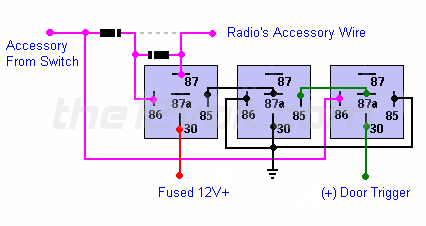
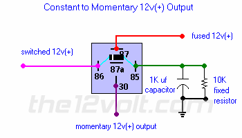
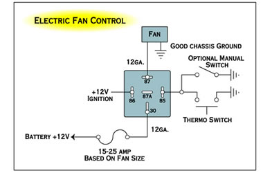
Example relay wiring schemes. Using the relay diagram above you can see that you can run a fused wire from your fuse.
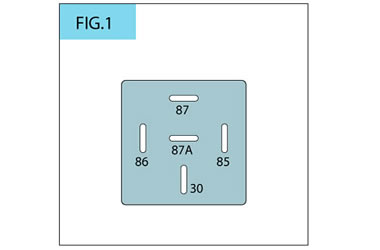
This pinout image is only a 2 pole diagram for room on the page purposes but you can get the picture here with this one since a 3 pole will just have 1 more set of contacts.
You can find out more Diagram below
12v 30a relay wiring diagram. Here is a picture gallery about bosch relay 12v 30a wiring diagram complete with the description of the image please find the image you need. Wiring diagram for 12v relay how to wire a 4 pin relay wiring throughout bosch relay 12v 30a wiring diagram image size 650 x 650 px and to view image details please click the image. 12 vdc automotive 5 pin relay spdt 3040a bosch type this bosch type 12v 40a relay is widely used in car sound and automotive security installations.
The relay above is a spst relay with dual outputs. Using relays to wiring off road lights and accessories. The relay features a plastic housing with mounting tab for easy installation.
The square relay pinout shows how the relay socket is configured for wiring. The relay will then switch in the alternator feed to the leisure battery to let it charge just like the vehicle starter battery. How to wire a relay 12v relays and how they work duration.
In the case of dual ratings the normally closed circuit is the lower of the two so 30a40a ncno for the example given. How to wire a 3040 amp relay thastunnamane. Using a 30 amp spdt relay connect terminal 87 to constant 12 volts positive with a fuse rated to the sum of the additional accessories youve added and the components you need to turn on.
Adding driving lights that come on with the headlight main beam. The following diagrams show some common relay wiring schemes that use 4 pin iso mini relays. I hope it.
Split charging relay smartcom voltage sensing the traditional method for split charging is to take a wire from the ignition to energise a relay when the engine is running. A few people have asked what gets connected to the different connectors on a relay. When 12v is applied between pins 85 and 86 the coil becomes a magnet which pulls the lever down making a connection between pins 30 and 87.
Connecting additional devices to the remote turn on wire relay wiring diagram. Well since i had an idea but wasnt 100 sure i did some reading and decided to do a quick vid. Spst relay single pole single throw relay an electromagnetic switch consist of a coil terminals 85 86 1 common terminal 30 and one normally open terminal 87it does not have a normally closed terminal like the spdt relay but may be used in place of spdt relays in all diagrams shown on this site where terminal 87a is not used.
12 volt planet auto.


0 comments:
Post a Comment