Principles of operation and safe practices for arc welding and cutting equipment we urge the heliarc acdc 281i 283i and 353i are state of. The ac welding machine design is a two pole circuit with the first pole been the primary circuit and the second pole is the secondar y circuit.
A block diagram of the system 2 circuit operations a block diagram of the system is shown in fig 2.

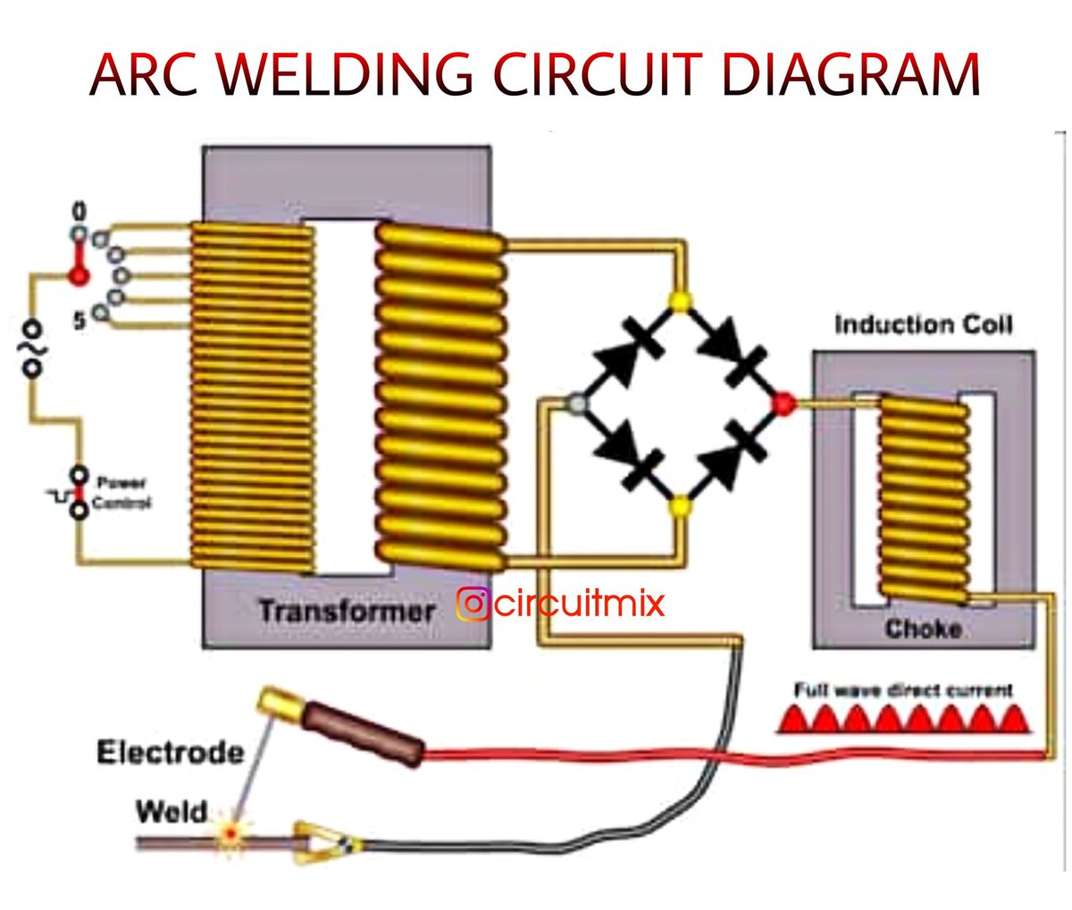
You can find out more Diagram below
Circuit diagram of arc welding machine. 21 the primary circuit pole 1. A sudden halt may occur while the welding operation is carried out while this welding machine is of over load status. Maintain a minimum distance of 30cm 12 between the inverter machine and any other objects in or near the working area.
The advantege is also that the output current is dc. The process of joining metal to metal with the help of an electric arc is called arc welding. Construction of welding transformer.
A secondary winding with less number of turns and high cross sectional area on the other arm. The first stage is a rectifier circuit that converts ac. This inverter welding machine.
Factory price professional manufacturer circuit diagram of welding machine model mains voltagev frequency hz no load voltagev rated input capacity kva cutting thickness mm output curreng a rated duty cycle dimensions weight cut 120i 380 5060 270 19 le40 20 120 60 56times37times35 25 cut 160i 380 5060 370 20 le50 20 160 60 67times33times51 60. A simple resonant circuit ac rectifier inverter arc starter arc main transformer output inductor fig 2. In this welding process the arc is used to create intense heat and this heat is used to join the metals together.
Here i describe how the power control circuit for my welder works and show the schematic diagram along with ideas for what parts to use. Martins welding arc welding machine circuit diagram arc welding machine lincoln ac dc welder wiring diagram. Due to this type of windings in primary and secondary it behaves as step down transformer.
Welding inverter up to 100a welding inverter is an alternative to a conventional welding transformer. The voltage feedback does not really hamper the welding. Typical output vi characteristic for arc welding supply fig3.
It has a magnetic core with primary winding which is thin and has large number of turns on one arm. Also i understand that its possible to use a dc stick welder as a scratch start tig i have a 20 amp 110v circuit out in the garage which would power the mig. Modern semiconductors allow to replace the traditional mains transformer with a switching power supply which is much lighter smaller and allows easy current adjustment via a potentiometer.
While l1 has ferrite ee core the middle column has the cross section of 16x20mm having 11 turns of copper strip of 36x05mm. 22 do not operate this machine when the oc. 20 homebuilt dc welder power control circuit.
Furthermore the total air gap and the magnetic circuit are set to 10mm and its inductance is 12uh cca.


0 comments:
Post a Comment